In this project, we will start to control the LED brightness analogly (not digitally[^1])touch base with the basics of running the board and provide simple visual feedback with a flashing LED.
[^1]: To put it simple, "digital" control can only make the LED on or off; with "analog" control, we can make the LED shine with different brightness.
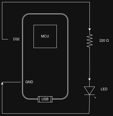
The 220 Ω resistor is a must, otherwise you will burn the LED.
No header file needed.
The main file is saved as main.cpp under the [project root]/src folder.
#include <Arduino.h>

constexpr int ledPin = 32;
constexpr int pwmResolution = 12;           // 12-bit resolution
constexpr int maxBrightness = (1 << pwmResolution) - 1;  // 4095
int brightness = 0;                         // current brightness
int fadeAmount = 30;                        // step size (scaled for higher resolution)

void setup() {
  analogWriteResolution(pwmResolution);     // set ESP32 PWM to 12-bit (0–4095)
  pinMode(ledPin, OUTPUT);
}

void loop() {
  analogWrite(ledPin, brightness);

  brightness += fadeAmount;

  // Clamp to avoid LEDC overflow flicker at boundaries
  if (brightness <= 0) {
    brightness = 0;
    fadeAmount = -fadeAmount;
  } else if (brightness >= maxBrightness) {
    brightness = maxBrightness;
    fadeAmount = -fadeAmount;
  }

  delay(15);
}
We have "upgraded" the Arduino sample a lot. Let me explain:
- As ESP32 is more powerful in all aspects than the Arduino (8bit), we have a bigger range of "How bright a LED can be" (or "resolution"). We set this to
int pwmResolution. - Thus, the max brightness is set using bit-op.
analogWriteResolution is new in ESP32 (or already there in Arduino?) and it sets the ESP32 PWM to 12-bit as defined.
The loop controls the fading/shining of the LED.
We put some truncating control over the brightness. If we don't put this control, and when brightness+= fadeAmount exceeds the upper limit, we will see a "flickering" of the LED.